As a supplier of power inductors, I’ve witnessed firsthand the critical role these components play in various electronic devices. Power inductors are essential for energy storage, filtering, and voltage regulation in circuits, making their performance a key factor in the overall functionality of electronic systems. In this blog, I’ll delve into the factors that affect the performance of a power inductor, providing insights that can help you make informed decisions when selecting the right inductor for your applications. Power Inductor
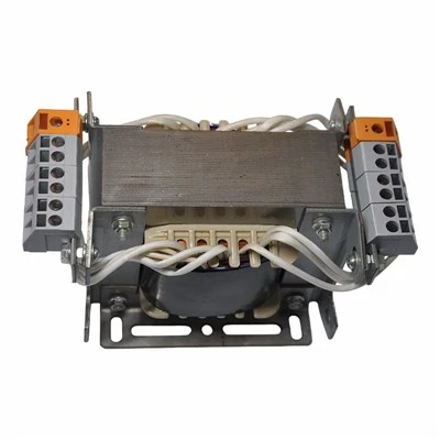
Inductance Value
The inductance value, measured in henries (H), is one of the most fundamental parameters of a power inductor. It determines the amount of magnetic flux generated by the inductor when a current flows through it. A higher inductance value allows the inductor to store more energy, which is beneficial for applications that require high energy storage, such as power supplies. However, a higher inductance value also means a larger physical size and higher resistance, which can lead to increased power losses.
The inductance value of a power inductor is influenced by several factors, including the number of turns, the core material, and the core geometry. Increasing the number of turns in the coil will increase the inductance value, but it will also increase the resistance and the physical size of the inductor. The core material also plays a crucial role in determining the inductance value. Different core materials have different magnetic properties, such as permeability, which affects the ability of the core to store magnetic energy. For example, ferrite cores have high permeability, making them suitable for high – frequency applications where a high inductance value is required in a small size.
Core Material
The core material is a critical factor that affects the performance of a power inductor. It provides a path for the magnetic flux generated by the coil, and its properties can significantly impact the inductor’s efficiency, power handling capacity, and frequency response.
Ferrite Cores
Ferrite cores are widely used in power inductors due to their high magnetic permeability and low core losses at high frequencies. They are made of a ceramic material composed of iron oxide and other metal oxides. Ferrite cores are suitable for applications such as switching power supplies, where high – frequency operation is required. However, ferrite cores have a limited saturation flux density, which means they can only handle a certain amount of magnetic flux before they saturate. Once the core saturates, the inductance value drops significantly, leading to increased power losses and reduced performance.
Powdered Iron Cores
Powdered iron cores are made by compressing iron powder particles together. They have a relatively high saturation flux density, which allows them to handle high currents without saturating. Powdered iron cores also exhibit low core losses at low frequencies, making them suitable for applications such as DC – DC converters and audio amplifiers. However, their magnetic permeability is lower than that of ferrite cores, which means they require more turns in the coil to achieve the same inductance value.
Iron Alloy Cores
Iron alloy cores, such as silicon steel and permalloy, offer a good balance between high saturation flux density and low core losses. They are commonly used in power inductors for applications that require high power handling capacity, such as industrial power supplies and electric vehicle chargers. However, iron alloy cores are more expensive than ferrite and powdered iron cores, and they are also heavier and larger in size.
DC Resistance (DCR)
The DC resistance of a power inductor is the resistance of the coil when a direct current (DC) flows through it. It is mainly determined by the material, cross – sectional area, and length of the wire used in the coil. A lower DCR is desirable because it reduces the power losses in the inductor, which in turn improves the efficiency of the circuit.
Power losses in the inductor due to DCR are calculated using the formula (P = I^{2}R_{DCR}), where (P) is the power loss, (I) is the current flowing through the inductor, and (R_{DCR}) is the DC resistance. As the current increases, the power losses due to DCR increase quadratically. Therefore, in applications where high currents are involved, such as high – power power supplies, it is crucial to select a power inductor with a low DCR.
Saturation Current
The saturation current is the maximum current that can flow through the inductor before the core saturates. When the core saturates, the inductance value drops significantly, and the inductor loses its ability to store energy effectively. This can lead to increased ripple current in the circuit, reduced efficiency, and potential overheating of the inductor.
The saturation current of a power inductor is affected by the core material and the core geometry. As mentioned earlier, cores with a high saturation flux density, such as powdered iron and iron alloy cores, can handle higher currents without saturating compared to ferrite cores. Additionally, increasing the cross – sectional area of the core can also increase the saturation current.
Ripple Current
Ripple current is the alternating current component that flows through the inductor in a switching power supply. It is caused by the switching action of the power transistors in the circuit. The ripple current affects the performance of the power inductor in several ways.
First, the ripple current causes additional power losses in the inductor due to the skin effect and the proximity effect. The skin effect causes the current to flow mainly on the surface of the wire, increasing the effective resistance of the wire. The proximity effect occurs when the magnetic fields generated by adjacent turns of the coil interact with each other, also increasing the resistance. These effects lead to increased power losses and reduced efficiency.
Second, the ripple current can cause the inductor to generate electromagnetic interference (EMI). The high – frequency components of the ripple current can radiate electromagnetic energy, which can interfere with the operation of other electronic components in the circuit. Therefore, it is important to select a power inductor that can handle the ripple current without generating excessive EMI.
Frequency Response
The frequency response of a power inductor is determined by its inductance value, core losses, and parasitic capacitance. At low frequencies, the inductance value of the inductor remains relatively constant, and the core losses are mainly due to hysteresis and eddy currents. As the frequency increases, the core losses increase significantly, especially for ferrite cores.
The parasitic capacitance of the inductor, which is formed between the turns of the coil, also becomes more significant at high frequencies. The parasitic capacitance can resonate with the inductance, causing a peak in the impedance of the inductor at a certain frequency. This resonance can affect the performance of the circuit, especially in high – frequency applications.
Temperature
Temperature has a significant impact on the performance of a power inductor. As the temperature increases, the resistance of the wire in the coil increases, leading to increased power losses. Additionally, the magnetic properties of the core material can change with temperature, which can affect the inductance value and the saturation current.
Most power inductors are specified with a temperature coefficient of inductance (TCI), which indicates how much the inductance value changes with temperature. A low TCI is desirable to ensure that the inductance value remains stable over a wide temperature range.
Physical Size and Packaging
The physical size and packaging of a power inductor are also important factors to consider. In modern electronic devices, there is a trend towards miniaturization, which requires power inductors to be smaller in size. However, reducing the size of the inductor can also affect its performance. A smaller inductor may have a lower inductance value, a higher DCR, and a lower saturation current.
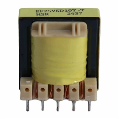
The packaging of the inductor also affects its performance. Different packaging types, such as surface – mount technology (SMT) and through – hole technology (THT), have different thermal and electrical characteristics. SMT inductors are commonly used in printed circuit boards (PCBs) due to their small size and high – density packaging. However, they may have lower power handling capacity compared to THT inductors.
Isolation Transformer In conclusion, the performance of a power inductor is affected by multiple factors, including inductance value, core material, DC resistance, saturation current, ripple current, frequency response, temperature, and physical size and packaging. As a power inductor supplier, we understand the importance of these factors and strive to provide high – quality inductors that meet the specific requirements of our customers. If you are looking for a reliable power inductor for your application, please feel free to contact us for a detailed discussion and procurement negotiation. We are committed to helping you find the best solution for your needs.
References
- Grover, F. W. (1946). Inductance Calculations: Working Formulas and Tables. Dover Publications.
- Montsinger, V. M. (1919). “Temperature and Voltage Limits of Insulation,” Transactions of the American Institute of Electrical Engineers, Vol. 38, pp. 1-16.
- Terman, F. E. (1955). Electronics and Radio Engineering. McGraw – Hill.
Dongguan Hensiron Electric Co., Ltd.
As one of the most professional power inductor suppliers in China, we have world-leading production equipment and strong manufacturing capabilities. Please feel free to buy high quality power inductor made in China here from our factory. Customized orders are welcome.
Address: Building 4, Xinxing Industrial Zone, Wangao Road, Wanjiang Street, Dongguan City, China
E-mail: jessica@dghensiron.com
WebSite: https://www.dghensiron.com/
